
 LOGIN
LOGIN Downloads


by James Head
To use the STEP files output from PCB Libraries Footprint Expert with Pulsonix make sure that the Vertical Axis in the Create Footprint dialogue is set to Z.
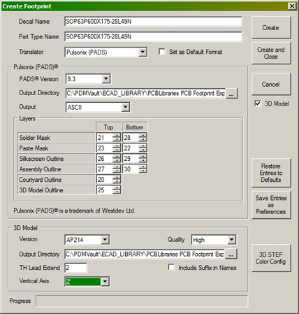
The Output Directory should be the same folder as set up in Pulsonix for STEP models.� This can be found in Pulsonix by selecting Setup Folders from the Menu bar.
After you have imported the footprint into the Pulsonix footprint library you need to set the value of the Component Attribute <STEP Filename> to match the name of the STEP file.�This can be done in any of the following ways:
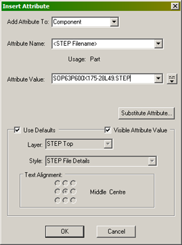
Insert Attribute
If you want a visible attribute on the footprint then from the menu bar select Insert Attribute and select <STEP Filename> as the Attribute Name, then enter the filename for the Attribute Value.
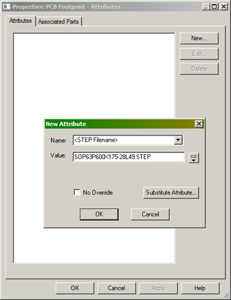
Design Properties
If you want an invisible attribute then when editing the footprint select Edit and Design Properties from the menu bar.
Make sure that the Attributes tab is selected and press the New button.
Select the <STEP Filename> attribute and enter the filename in the Value text entry box.
Library Manager Attributes
The third method of adding the STEP filename is more useful if you have many footprints to go through but it relies on at least one footprint in the list already having the <STEP Filename> attribute saved.
Bring up the Library Manager by selecting Setup and Libraries from the menu bar and select the PCB Footprints tab.
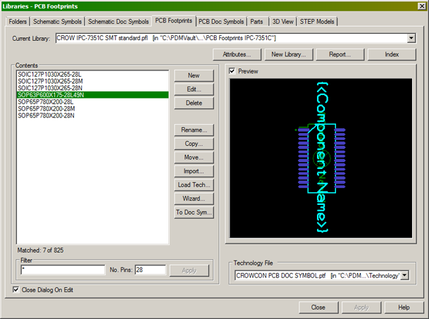
Select the footprint or footprints that you want to edit or enter STEP information for, and press the Attributes button.
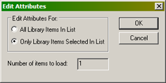
You'll then be asked if you want to show attributes for every footprint in the selected library or just the footprints you've selected.
A spreadsheet view of footprints and attributes will now be shown.
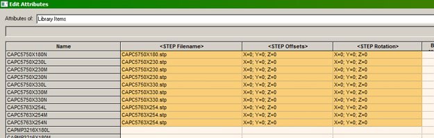
The user can enter values for the attributes <STEP Filename> <STEP Offsets> and <STEP Rotation> by typing directly in the cells and then pressing the Apply button to write the values to the footprints in the library.
For neatness the user can enter values of X=0; Y=0; Z=0 for both the <STEP Offsets> and <STEP Rotation> attributes.
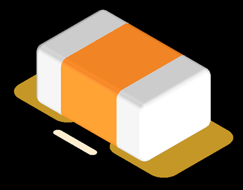
Viewing the STEP file in the footprint
To view the STEP file in Pulsonix, open the footprint in the Footprint Editor and select View and View STEP. This is a useful check to make sure the STEP rotation and offsets are acceptable.
Footprint Expert 2012, 2013, 2014 and IPC-7351 Level A Rotations
If you are using a version of PCB Libraries Footprint Expert prior to 2015 and the IPC-7351 Level A rotation then the rotation of components such as SOIC, SOP, SOT-23, QFP, and QFN devices will not match the rotation of your footprint.
You will need to adjust the value of the <STEP Rotation> attribute for Z to make the STEP file align on the footprint correctly.
PCB Libraries Footprint Expert 2015 outputs the STEP file to match the rotation of the output footprint so the default value of X=0; Y=0; Z=0 will suffice.
In these cases a SOP or SOIC footprint will typically require a value of X=0; Y=0; Z=270 and a SOT-23 device will require a value of X=0; Y=0; Z=180 for the <STEP Rotation> attribute.
