
 LOGIN
LOGIN Downloads


FPX files are ASCII data files used by the Footprint Expert to store electronic part data. The main purpose of an FPX file is to store component package dimensions and the component manufacturer's recommended pattern data. Here is a list of 9 attributes items that are default with the PCB Footprint Expert -
- Component Family (auto-generated but not a visible column in the FPX editor)
- Component Dimensions (auto-generated but not a visible column in the FPX editor)
- Footprint Name (auto-generated by the Footprint Expert)
- Physical Description (auto-generated by the Footprint Expert)
- Case Code (component manufacturer's ID of the package)
- Manufacturer (component mfr. company name)
- Part Number (manufacturer's Logical part number)
- Logical Description (component manufacturer's logical description)
- Mounting Type (Surface Mount, Through-hole, Mixed Technology)
- Datasheet (http:// web-link or network drive link + PDF file name)
- Part Status (Active or Obsolete)
- Footprint Date (Last date the footprint was updated)
- Comments (User defined information)
- Columns 1 - 4. 9 & 12 are auto generated by Footprint Expert
- Columns 5 - 8, 10 & 13 are inserted by the end user (used as search criteria)
The PCB Footprint Expert User can add as many attribute columns as necessary. Some of the most popular additional columns are "Revision or Version Control", "Supplier Name and Part Number" (Digi-Key), "Schematic Symbol Name", "Created By", "Corporate Part Number" and so on.
The FPX file does not contain any user Options or footprint dimensions. It is important that the Footprint Expert end user knows that the main items to generate a footprint are the component family and package dimensions. This means that you cannot import your existing CAD tool library into an FPX file.
The User Option Rules are applied to the component package dimensions to auto-generate a Footprint pattern for the PCB library.
The component family and package dimensions are stable data that never changes. The User can continuously add new component dimensions to the FPX and never have to go back and change anything.
The User Option Rules are continuously changing as manufacturers continue to improve their processes. At any time, the Footprint Expert User can make a change to their Option Rules and run all their component dimensions through those new rules and create a new library. The Option Rules may change at any time, but the FPX file never changes except to continually add additional package data.
There is no limit of how many parts can be put in an FPX file, but certain features are slow if the FPX file gets too big. To achieve maximum software performance, we recommend not exceeding 5,000 parts in an FPX file.
There are 5 footprint features that are stored in the FPX file.
1. Package Dimensions
2. Manufacturer's Recommended Pattern dimensions
3. Manually inserted polarity markings
4. 3D STEP Colors
5. Footprint Rotation
All other footprint features are stored in "Tools > Options".
Here is a sample FPX file loaded in the Footprint Expert FPX Editor -
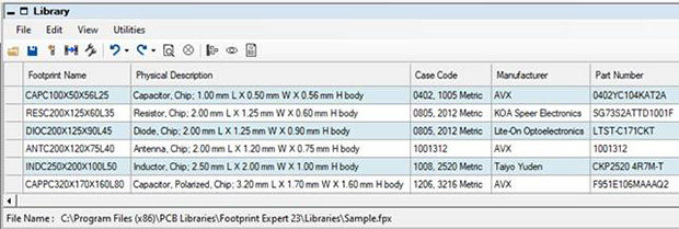
The column data that the User inserts comes directly from the component manufacturer Logical datasheet. Using this Texas Instruments datasheet as an example, the number in the upper right corner is the "Part Number" and the text below the part number is the "Logical Description".

Included in the Logical datasheet are the component package dimensions. On the package dimension page in the datasheet is the manufacturer's Case Code. In this TI datasheet the Case Code is in the upper left corner.
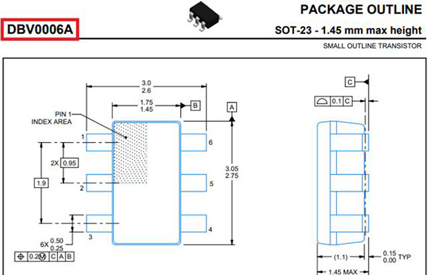
The sample Datasheet URL is https://www.ti.com/lit/ds/symlink/sn74aup1t97.pdf and includes both the Logical and Physical data for the electronic device.
