LOGIN
LOGIN Downloads


1. Configure the Cadence Paths
These steps specify the configurations needed to have the Footprint Expert output Footprints and 3D STEP models into Allegro or OrCAD PCB.
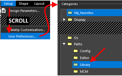
Open Allegro or OrCAD PCB and select Setup > User Preferences
Select Paths and the Library category.
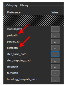
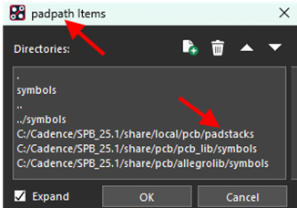
Set your padpath and psmpath to point to your current working
directory. Click the "..." button to expand.
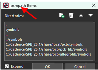
At the top of the padpath list choose New (Insert) and place a "." (period) as the Directory name. Next, move the "." to the top of the form. Ensure you also have ".." as shown in the image below.
Select "OK" when complete. Repeat for the psmpath. This sets the current directory as a searchable path for proper linkage when running the main script created by Footprint Expert.
Both forms should look similar to this:
2. Turn off the Drill Warnings
NOTE: If you do not see the following menu options, skip to Section 3.
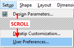
In your Cadence application, go to Setup > User Preferences.
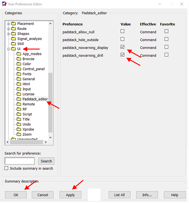
Choose UI then in the tree on the left, Pad_designer option (or Padstack_editor for versions 17.2 or higher).
Set the padstack_nowarning_drill and padstack_nowarning_display to checked.
NOTE: Non-plated pad stacks will always have a pad smaller than the drill. With this checked, those warnings will be automatically bypassed. If you do not do this, you will need to save the pad stack with warnings. A process which must follow Section 3 exactly.
Click Apply and then OK to close the window.
3. Bypass Drill Warnings
NOTE: This step is only necessary if you could not complete the steps in Section 2,
and later tried to generate a part with a non-plated pad stack. In this
situation, you will get the following warning:
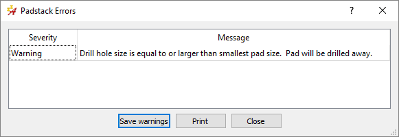
To bypass this, you cannot simply click the "X" of the Pad Stack Warnings window and then close pad_designer. The .pad file will not get generated and when the Footprint Script goes to draw the pins it will not be able to link to the proper pad stack. Instead, it will either use the latest pad stack it could generate, or no pad stack at all. Either way, it will be wrong.
To avoid this, following these 5 steps every time you see the above window.
1. Close the Warning (Using the 'X' is fine)
2. Select File > Save in Pad Designer
3. Close the Warning again
4. Click Yes to Save the Pad Stack with Warnings
5. Close Pad Designer
This generates the .pad file properly and when the footprint script attempts to link to it, it will be successful.
4. Understanding the Options
For both Allegro and OrCAD PCB, there can be anywhere from 8 to 10 options you should
understand:
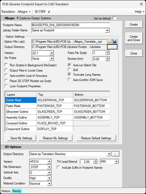
- Version: Drop-down that sets the version of Allegro or OrCAD PCB you currently use.
- Output Directory: This is the directory which will contain sub-directories named after each footprint name. Footprint files are saved to its respective subdirectory.
- Parts Per Script: This is typically used when generating lots of parts at once. For example, if you are generating 100 parts, with this value set to 1, the program will open and close 100 times (once for each part). If you set this to 100 parts per script, the script would generate 100 parts, but open and close Allegro only once. It will save a lot of time when batch processing, but for most implementations where only a handful of parts are generated at one time, it is suggested that you use the default.
- No Probe: This will place a shape on the No Probe layer that will match the selected constraints. The options for constraints are Component Body, the Footprint Extents, or the Courtyard.
- Excess: This expands or contracts the No Probe extents by a static amount in millimeters. This has no effect if No Probe area is not selected.
- Run Scripts in Background (NoGraph): This turns off the graphic display of the programs being run. This does have a major downside in that if there is an error, you will not be able to see it. Its particularly problematic if you run multiple licenses of various Allegro tools that provide a selector window. In that case, this must be turned off so you can select the proper tool, or the script will appear to be 'hung'. It's just waiting for input at the selector window as to which tool you want to run, but you will not see that selector window if you have it running in the background. This is off by default (and recommended to remain off), particularly given that you can watch the scripts draw the parts.
- Output Files in Lower Case: The script files will all be forced to lower case.
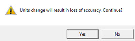
- Auto-confirm Loss of Accuracy: When the pad_designer runs,
there is a quirk in some versions of Allegro will provide a message prompt
for changing of the units, while others will not. To set this properly, set it to
off. When the part goes to process and runs in pad_designer, if you
see the following window, turn this option on and select the Save Entries as
Preferences button. Once this is done, this will be auto-confirmed.
- Place 3D STEP Models Via Script: This is only usable if your license for Allegro supports 3D Modeling. If it does not, turn this off. If it does, what this will do is insert the model (for any standard component package) into the footprint just before script completion.
- Auto-Confirm SSM Save: Certain versions of Allegro will pop a confirmation box when a SSM (complex pad stack) goes to save. This option is to allow auto-confirmation if you have one of those versions. By default this is off, but you may want to turn it on if you get annoying confirmation boxes at the end of a complex pad stack save. If you do not get confirmation messages, simply leave as default.
- Autorun Batch File: The program generates a set of files in the Output Directory. Among the script files generated is a batch file (.BAT) that must run, which invokes Cadence to process the script files generated. If this option is on, the Footprint Expert will attempt to invoke the batch file so it immediately runs once the script translation is complete.
- Skill: Typically unused, normally turned off.
- Truncate Long Names: Certain versions of Allegro have a 30-character limit for names. Try running with it turned off, and if it has issues, turn it on. As such, this will keep the file names under the limit.
Importing to Cadence
The files below were created in a sub-directory (located in specified Output Directory); this
sub-directory is named after the footprint name. All pertinent footprint files will be placed in
this new directory (in the example, "CAPC100X50X56L25N"):
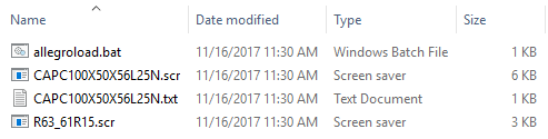
- .psr: A pad_designer script which generates the pad stacks. These will be labelled .scr in v17.2 or later.
- .txt: Device file used by Cadence.
- .scr: Script for Cadence, which draws the final footprint and places the pad stacks that were generated into the final DRA and PSM footprint files.
- .bat: Batch file which invokes Cadence and runs each of the scripts in order to generate the final output. It first runs the pad_designer and generates the pad stacks, then it runs the full Cadence tool and generates the part itself using those pad stacks.
Certain parts also have complex pad stacks; these get generated before the regular pad stacks, but the purpose here is to give you a higher-level view of the process and not go too deep in detail.
To processing the Script files, (if you do not have Auto-run option enabled), simply run either Allegroload.bat or Orcadpcbload.bat depending on your output, and the batch file should take care of the rest.
Troubleshooting and Tips
- Verify Pad Stack is Created
For Version 16.0, current ISR
is required. Check Help > About - if the release is Version 16.0 Pxxx then it is
the base release. Download current HotFix from Cadence.
- Pad stack created and no pad in symbol: verify padpath is pointing to the directory that FPX is running, as shown in Section 1.
- Multiple Versions of Allegro Installed: Is the PATH pointing to the correct version? Sometime between Allegro 17.2 / 17.4 there was a change so that when you first create a new PCB footprint using script files, there is a new Windows message box that pops up asking for design information. When these pops up, it stops the script file. There is a setting in Allegro / OrCAD that disables this Windows message box from opening. Check the following checkbox: 'Setup > User Preferences > Drawing > New_design > orcad_no_new_design_form'
- Files to Aid in Trouble Shooting
Defined variables from Allegro. This lists the install path, working directory, system path.
Setup > User Preferences > List all save to text file
Journal files (recordings of current executed commands) usually located in working directory.
allegro.jrl (list Allegro commands and can indicate errors)
pad_designer.jrl (list pad designer commands and can indicate errors)
- SKILL: Scripts that include SKILL will only execute by Allegro L w/Performance and above.
- Proper Version: For any footprint issue or error, ensure you selected the proper Cadence version. For example, footprints created in version 25 can NOT be used in version 17.
- File Retention: After the footprint is generated, the *.DRA, *.PSM and *.PAD files are created and package symbol is verified, the script / builder files can be deleted as desired. You can automatically regenerate these from the Footprint Expert later as needed.
- BRD File prompt: If you are prompted for a BRD file when trying to 'Autorun' from the Footprint
Expert, close the Footprint Expert and restart it on its own from the installed
directory or a Footprint Expert shortcut, do not start it from the EDM Flow
Manager. Then try again to create the script and 'Autorun' it.
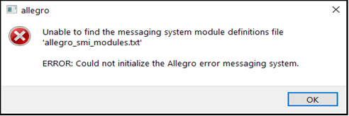
- Error Messaging System: If you get "ERROR:Could not initialize the Allegro error messaging system." - perhaps with reference to messaging system module definitions file 'allegro_smi_modules.txt', it could be that the Cadence env file/environment file is somehow corrupted. Try to delete the env file so that Cadence creates a new one from scratch.
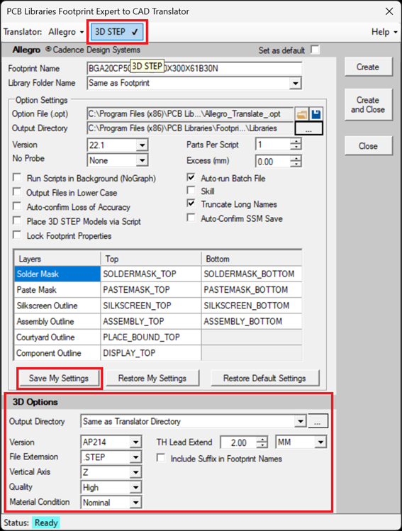
3D STEP Notes
To create a 3D STEP model for any standard package, make sure "3D STEP" is on (in the Footprint Expert by selecting the "3D STEP" checkbox as shown below. Ensure configuration in the flyout the 3D Options section, and click 'Create' or 'Create and Close'.
In Allegro (provided you have 3D functionality as part of the Allegro License), select
'Place 3D Models via Script' and save it as a preference.
Microsoft Windows Settings
Check the following Windows settings to make sure the calls to the binaries can be located by your system when the script runs. If the script runs without issues, this should be fine. If the script fails to run, your Windows settings most likely need to get validated as follows:
In Windows, type System in the search box or go to Control Panel > Advanced System Settings > Environment Variables
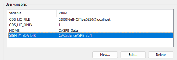
Check your User Variables for SIGRITY_EDA_DIR.
Confirm this drive/directory exists by navigating in Windows File Explorer. If
it is different, specify the value of this variable accordingly. If it is missing,
you'll need to click 'New' to add it here, and give it the path to the
SPB directory for the location and version of your Cadence installation.
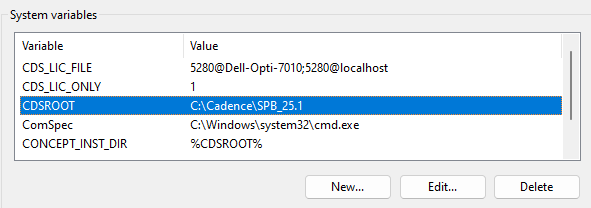
Check your System Variables for CDSROOT.
Confirm this drive/directory exists by navigating in Windows File Explorer. If
it is different, specify the value of this variable accordingly. If it is
missing, you'll need to click 'New' to add it here, and give it the path
to the SPB directory for the location and version of your Cadence installation.
Check your System Variables for CONCEPT_INST_DIR.
Edit this variable so it is as shown above. If it is missing, you'll need to
click 'New' to add it here, and give it the value shown above.
Check System Variables to verify the specified paths exist and are accurately specified.
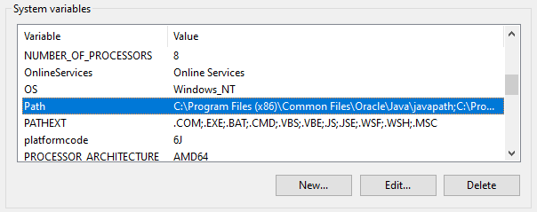
Select the 'Path' variable and click the 'Edit' button.
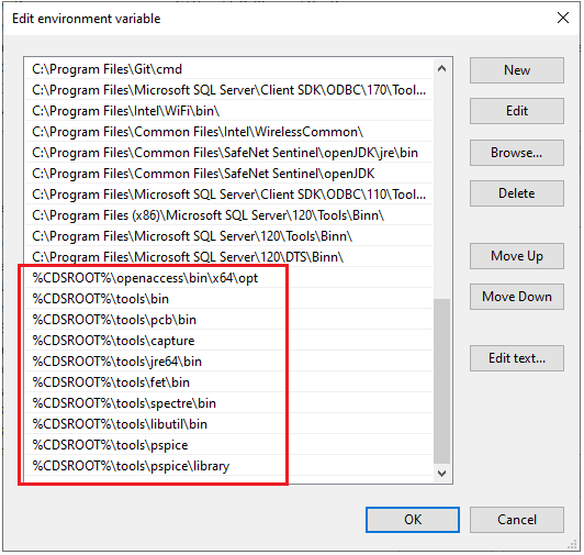
You may see the following paths that start with %CDSROOT%.
If you do not see any %CDSROOT% entries, you can add all the defaults in a few easy steps:
Click the 'Edit text' button (not the Edit button!)
Copy and paste the full path into notepad and copy and paste the following string onto the end
of it. Make sure to separate it by a semicolon. Then take the new Path and copy
and paste it back into Edit Text and click OK.
If done proper, you should now see those directories at the end of the Environment Variable list. If you prefer to go step by step (not the bulk update via the 'Edit text' button, click New to enter any missing values, confirming the directory you use actually exists in Windows File Explorer.
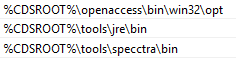
NOTE: Alternate values may depend on your installed version and PC/operating system version. You may require different values. You can tell what values you need by paying particular attention to the format and spelling of the values. Confirm each drive/directory exists by navigating in Windows File Explorer in the previously specified CDSROOT directory (see above). If any of the directories are different, modify the respective value accordingly.
For example, older installations and computers may require slightly
different values; you can confirm by navigating to these directories
in your Windows File Explorer:
These Path linkages allow your system to know where 'padstack_editor' is when issued as a command to convert the SCR files to DRA and PSM. The first sets up a variable to refer to the Cadence Design System Root (CDSROOT) directory, and the second uses that to put various directories in the Path. Both the Padstack Editor and Allegro itself should be found in the tools\bin directory.
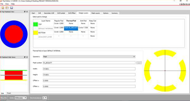
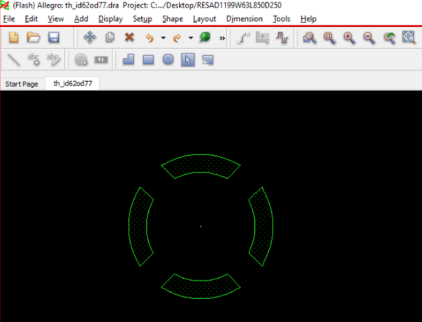
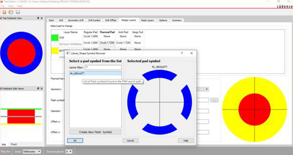
CADENCE THROUGH-HOLE THERMAL RELIEF
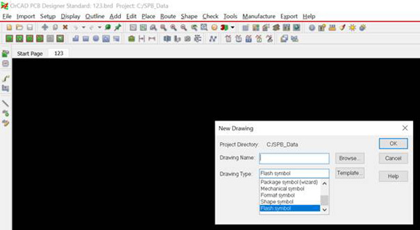
1. Create a New Flash Symbol by navigating to File > New > Flash Symbol
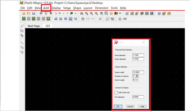
2. Add the Flash Symbol by navigating to Add > Flash, then enter the required parameter values from the FPX file, and save the Thermal Relief
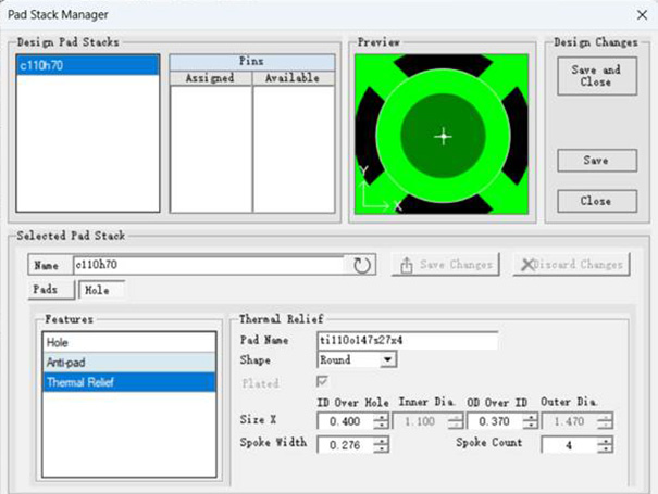
3. Open and edit the corresponding Pad Stack, apply the Thermal Relief Symbol, and save the updated Pad Stack
Final Pad Stack result: