Design Units
Printed From: PCB Libraries Forum
Category: Libraries
Forum Name: PCB Libraries Guideline
Forum Description: (online edition)
URL: https://www.PCBLibraries.com/forum/forum_posts.asp?TID=3689
Printed Date: 05 Oct 2026 at 2:44pm
Topic: Design Units
Posted By: Nick B
Subject: Design Units
Date Posted: 20 Aug 2026 at 11:00am
|
PCB Footprint Expert Design Units User Interface 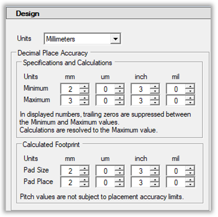 There are 4 options (millimeter, micrometer, inch, mil) for units, but millimeter is the most popular today because most package dimensions in manufacturer datasheets are displayed in millimeter units. Decimal Place Accuracy > Minimum / Maximum Most PCB Library Parts are created in millimeter units to match the current package datasheet, but everyone is in a different environment. The new "Units" allows you to set the Minimum and Maximum rounding values. By setting the Minimum and Maximum values, you establish the program rounding values. Example 1: using 2 place Minimum accuracy, entering a 0.8 value, will display as 0.80. The program will automatically add a trailing zero to round the value 2 place minimal accuracy. Example 2: using 2 place Maximum accuracy, all values will be rounded up to the nearest 0.01. Entering a 0.025 value would display as 0.03. The program default settings are Minimum 2 and Maximum 3. Because the minimum is 2, the program will automatically remove all training zero’s past 2 places. And the maximum setting of 3 will only round up values less than one micrometer. Example 3: using a 3 place Maximum accuracy, a value of 0.3255 will be rounded up to 0.326 Example 4: using a 2 place Minimum accuracy, a value of 0.29 will be rounded up to 0.30
The most important thing is that both the minimum and maximum options go up to 6 places. This accuracy is intended to increase the rounding accuracy when converting between Metric and Imperial units. It is not recommended that users select 6/6 as their min/max because this will affect the Physical Description that is auto generated by Footprint Expert in the FPX file. Having every value 6 places to the right of the decimal point would also affect every component family calculator, as every value will be rounded and displayed with 6-point accuracy. A simple value of 0.01 would display as 0.010000 and the Physical Description would be the same. 
 The Footprint Expert automates footprints to perfection. Professional, detailed, and accurate parts - all built consistently with identical rules, regardless of how many people are involved in your library development. Get your FREE Footprint Calculator or Footprint Expert Evaluation License: https://www.pcblibraries.com/Register" target="_blank rel="nofollow" - https://www.PCBLibraries.com/Register Call us - 847-557-2300 ------------- Stay connected - follow us! https://twitter.com/PCBLibraries" rel="nofollow - X - http://www.linkedin.com/company/pcb-libraries-inc-/" rel="nofollow - LinkedIn |