Altium Mechanical Layers
Printed From: PCB Libraries Forum
Category: PCB Footprint Expert
Forum Name: Questions & Answers
Forum Description: issues and technical support
URL: https://www.PCBLibraries.com/forum/forum_posts.asp?TID=3573
Printed Date: 11 Jul 2026 at 1:39am
Topic: Altium Mechanical Layers
Posted By: m.elsayed
Subject: Altium Mechanical Layers
Date Posted: 04 Nov 2025 at 6:50am
I setup my Altium output for Mechanical Layers 11, 13, 15 only. 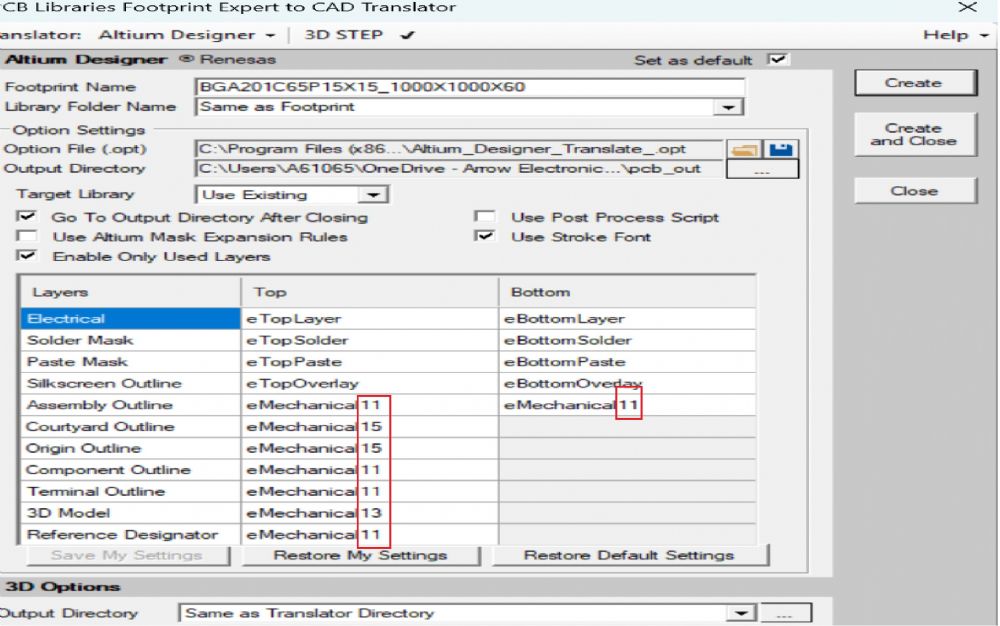 However, when open in Altium it appears extra layer Mechanical 1 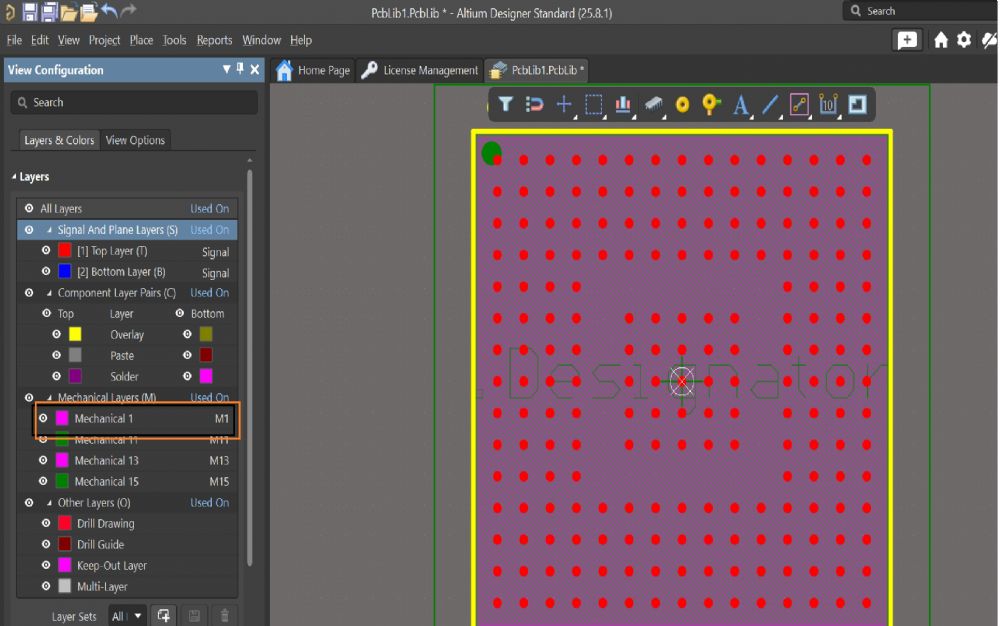 |
Replies:
Posted By: dramos
Date Posted: 04 Nov 2025 at 7:46am
|
Hi m.elsayed, Really interesting issue. We configure our mech stack in PCBFootprint Expert as well... is this mechanical 1 the Assembly Bottom layer?Regards. david |
Posted By: Tom H
Date Posted: 04 Nov 2025 at 8:24am
|
Here are the Altium Default Layer Assignments created in November 2024. https://octopart.com/documentation/style-guide/altium-designer-specific#layers-in-altium-designer" rel="nofollow - https://octopart.com/documentation/style-guide/altium-designer-specific#layers-in-altium-designer These are the Default Layers in Footprint Expert. Here is the Altium documentation information to their Style Guide: https://octopart.com/documentation/style-guide" rel="nofollow - https://octopart.com/documentation/style-guide In your screenshot, you are assigning Mechanical Layer 11 to the Assembly Outline Top and Bottom. This is not recommended that you use the same layer for both Top and Bottom. You are also assigning Component Outline, Terminal Outline and Reference Designator to Mechanical Layer 11. Never seen this before and we don't know any professional Altium user who directs all these elements to the same Mechanical Layer 11. We highly recommended that you use the Altium Default Layer Recommendations. ------------- Stay connected - follow us! https://twitter.com/PCBLibraries" rel="nofollow - X - http://www.linkedin.com/company/pcb-libraries-inc-/" rel="nofollow - LinkedIn |
Posted By: m.elsayed
Date Posted: 05 Nov 2025 at 1:00am
|
Tom, This is a customized layer option we need. Mechanical layer 1 appears as blank layer however, we don't need it. It's in the Script. Can please check? |
Posted By: Jeff.M
Date Posted: 05 Nov 2025 at 9:32am
|
The FPE Altium translator only writes mechanical layer 1 to the .pas script when a user assigns Altium eMechanical1 to one of the FPE Footprint layers (like 'courtyard' or 'silkscreen'). Unspecified layers will never appear in a translator script. If you have a question or issue with layer 1 as applies to your Altium application, then you need to contact Altium. ------------- Stay connected - follow us! https://twitter.com/PCBLibraries" rel="nofollow - X - http://www.linkedin.com/company/pcb-libraries-inc-/" rel="nofollow - LinkedIn |
Posted By: Tom H
Date Posted: 09 Nov 2025 at 4:26pm
|
Default Altium Layers. Mechanical Layer 1 = Board Shape
Layers in Altium Designer The following Altium layer mapping is suggested as a
standard. This mapping includes the Layer Type settings available in the Edit
Layer dialog in Altium Designer for both single mechanical layers as well as
for layer pairs. When there are two consecutive similar layers where the first
layer begins with TOP…, and the next layer begins with BOTTOM…, these two
layers should be used to create a corresponding layer pair in Altium Designer.
For example, Mechanical Layer 9, TOP GLUE, and Mechanical Layer 10, BOTTOM
GLUE, would be used to create a Layer Pair called GLUE with the Layer Type
setting set to Glue Points. Layer Types make it easier to share Altium Designer data
when different layer numbers have been used for the same layer information by
different users. For example, one uses Mechanical Layers 13 and 14 for Top and
Bottom 3D Bodies, and the other uses Mechanical Layers 14 and 15 for Top and
Bottom 3D bodies. 3D body data could potentially be lost when sharing between
the two users. However, if both users have assigned the Layer Type of the 3D
body to their respective 3D body layer pair, then when loading data from each
other, the 3D body data will be mapped to the corresponding layer numbers that
match the Layer Type. See Working with Mechanical Layers” in the Altium
Designer online documentation for more information. This layer mapping also includes some basic layers needed
for Flex and Rigid-Flex PCB designs.
------------- Stay connected - follow us! https://twitter.com/PCBLibraries" rel="nofollow - X - http://www.linkedin.com/company/pcb-libraries-inc-/" rel="nofollow - LinkedIn |
|||||||||||||||||||||||||||||||||||||||||||||||||||||||||||||||||||||||||||||||||||||||||||||||||||||||||||||||||||||||||||||||||||||||||||||||||||||||||||||||||
Posted By: m.elsayed
Date Posted: 11 Nov 2025 at 7:27am
|
I communicated with Altium and their reply as below. Please advise and support. "If you create a new footprint (which the script seems to do) or even a new PCB, per default there is a Mechanical Layer 1. But to be honest, all mechanical layers from 1 to 32 are predefined. They already exist. They are not visible in the View Configurations, but they are sort of already there (only visibility is false). So it is basic Altium functionality to have this layer there. In your Footprint, go to Tools > Export Mechanical Layers. Generate the .stackup file. Now open the stackup file with a text editor. You will find that the Mechanical Layers are there, but visibility is set to false. So there is no issue in having the Mechanical Layer visible. But to me it seems if you want the mechanical layer to be disabled automatically, make it so in the script that it is removed after the mechanical layers. |
Posted By: Tom H
Date Posted: 11 Nov 2025 at 9:30am
|
We don't have any plans on updating the Altium script routine. It’s a unique custom modification that has never even been suggested by any of our Altium users and may not be benign or welcomed by our Altium customers. ------------- Stay connected - follow us! https://twitter.com/PCBLibraries" rel="nofollow - X - http://www.linkedin.com/company/pcb-libraries-inc-/" rel="nofollow - LinkedIn |
Posted By: m.elsayed
Date Posted: 12 Nov 2025 at 12:26am
|
Thanks Tom for great your support Just note this is not custom modification, M1 is added as blank by defualt when you pcb, file before strat run scrpit, so supposed that when scrpit open before load data delet balnk layer which added by default and keep only M layers which result from pcb tool
|