

|
|
Courtyard Excess |
Post Reply 
|
| Author | |
Nick B 
Admin Group 

Joined: 02 Jan 2012 Status: Offline Points: 2066 |
 Post Options Post Options
 Thanks(0) Thanks(0)
 Quote Reply Quote Reply
 Topic: Courtyard Excess Topic: Courtyard ExcessPosted: 15 Aug 2026 at 11:00am |
|
In PCB design, courtyard excess refers to the specific clearance area between the combined physical boundary of a component (body and pads) and the outer boundary of its placement courtyard. This buffer zone ensures that components have sufficient space for manufacturing tolerances, mechanical assembly, and potential rework without interfering with neighboring parts. Courtyards should not overlap in the part placement. Courtyards are used in a variety of ways in different CAD tools. The courtyard excess values are defined in the 3-Tier density levels for surface mount components.
The default courtyard outline maps to the pads and the Maximum package body dimensions. Mapping the courtyard outline to Maximum package body dimensions is affected by package tolerances. Package tolerances vary between component manufacturers affecting the resulting courtyard excess value. There is a Drafting Option switch to change the courtyard outline to map to the Nominal package body. Using Nominal package body is not affected by package tolerances and provides a consistent courtyard excess for all footprints regardless of the package tolerance values. IPC-7352 only recommends mapping to the Maximum package dimensions, but industry consensus is leaning toward using Nominal package dimensions because component manufacturer tolerances are sometimes too robust and unrealistic. For through-hole component footprints, the courtyard excess is set to a single value because through-hole technology only has a single density level. The typical through-hole courtyard excess is 0.25 mm. Requirements for Special Component Types While generic components follow standard density levels, certain parts require larger excess values due to their physical height or specialized assembly needs:
Why Courtyard Excess is Critical
The courtyard excess for component body and footprint pads can be independently adjusted. The main reason for 2 different settings is because the physical package can move in any direction during reflow oven, but the pads never move. Typically, the courtyard to body and courtyard to pad are set to the same value for symmetry, but they can be adjusted to the individual user. There is also a manufacturing allowance provided by the assembly shop as a courtyard-to-courtyard clearance rule. In the average case, courtyards can be bumped next to each other. But the assembly shop may provide a spacing rule between courtyards, and this is referred to as the manufacturing zone. 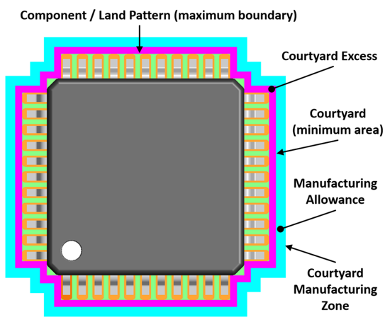 The original courtyard shape in IPC-SM-782 was rectangular. The contour courtyard was introduced in the IPC-7351 guideline. The Footprint Expert can automatically switch between either courtyard outline shape, and rebuild your entire library with whatever you choose. |
|
 |
|

|
|
|
|
|
Post Reply
|
|
| Tweet |
| Forum Jump | Forum Permissions You cannot post new topics in this forum You cannot reply to topics in this forum You cannot delete your posts in this forum You cannot edit your posts in this forum You cannot create polls in this forum You cannot vote in polls in this forum |


 Topic Options