Chip Land Pattern Zero Rotation Chip Antenna

| Chip Capacitor
| Chip Inductor
| Chip Varistor
| Chip Resistor
| Chip Fuse
| Chip Non-polarized Diode
| Chip Filter
| Chip Ferrite Bead

| Chip Diode
| Chip Thermistor
| Chip LED
|
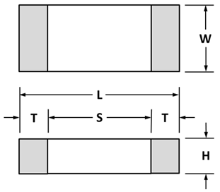
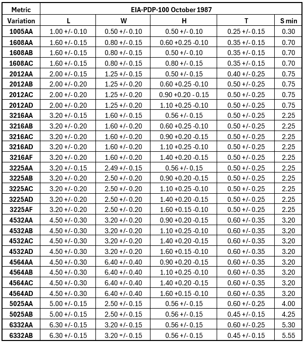
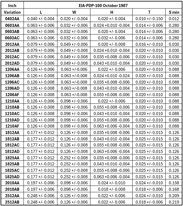
EIA-PDP-100 for Chip Components (published October 1987)
EIA-PDP-100 Chip package dimensions:
EIA is the 'Electronic Industries Association'. EIA published the first standard dimensional data for chip component packages. Purchase a PDF copy of the EIA PDP-100-1987: Registered & Standard Mechanical Outlines for Electronic Parts for $7.50 here: https://www.normisland.com/
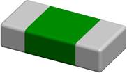
Chip Antenna A chip antenna is a compact, surface-mountable electronic component designed to transmit and receive high-frequency radio waves in wireless devices. Valued for their small footprint, low profile, and cost-effectiveness, they are ideal for space-limited applications such as smartphones, wearable devices, and Wi-Fi routers.
Design and Function Chip antennas function by creating a standing wave of an electrical field within a ceramic dielectric material (which has a high permittivity), allowing them to resonate at specific frequencies while being much smaller than traditional antennas designed for the same wavelength in free space. - Construction: They are typically manufactured using Low-Temperature Co-fired Ceramic (LTCC) technology, integrating metal layers within a ceramic body.
- Ground Plane Dependency: Chip antennas are dependent on the device's printed circuit board (PCB) ground plane to form a complete resonant circuit and achieve optimal performance.
- Impedance Matching: To ensure maximum power transfer and efficiency, a matching network (often a Pi-network with capacitors and inductors) is used to optimize the impedance between the antenna and the radio frequency (RF) circuit.
- Performance Factors: The antenna's performance is highly influenced by its placement, the size and shape of the PCB ground plane, the device's enclosure (especially metal components), and the presence of nearby components.
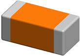
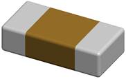
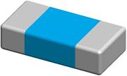
Chip Capacitor A chip capacitor, also known as a surface-mount device (SMD) capacitor, is a miniature electronic component that stores electrical energy in an electric field. These components are designed to be mounted directly onto the surface of printed circuit boards (PCBs), enabling the miniaturization and high integration of modern electronic devices like smartphones and computers.
Function and Operation The primary function of a capacitor is to store electrical charge. This is achieved by using two conductive plates separated by an insulating material called a dielectric. - Energy Storage: When a voltage is applied, charges build up on the plates, creating an electric field across the dielectric. The amount of charge stored is proportional to the applied voltage and the component's capacitance.
- AC vs. DC: Capacitors block the flow of direct current (DC) once charged, but allow alternating current (AC) signals to pass through, a key property used in filtering and coupling applications.
- Rapid Charge/Discharge: Unlike batteries, which store energy chemically, capacitors store energy physically in an electric field, allowing them to charge and discharge extremely quickly.
- Filtering: In power supplies, capacitors act as reservoirs, smoothing out voltage fluctuations (ripples) by charging during voltage peaks and discharging during valleys, ensuring a stable DC output.
Common Types of Chip Capacitors Chip capacitors come in various types, primarily differentiated by their dielectric material, which determines their characteristics and suitability for different applications. - Multilayer Ceramic Chip Capacitors (MLCCs): The most common type, MLCCs use alternating layers of ceramic and metal electrodes.
- Features: Non-polarized (can be connected in either direction), wide range of capacitance values, high frequency performance, and low Equivalent Series Resistance (ESR).
- Dielectrics: Common ceramic dielectrics have specific temperature characteristics, such as NP0 (C0G) for high stability or X7R/X5R for higher capacitance in a smaller size, though with less temperature stability.
- Tantalum Chip Capacitors: These polarized capacitors offer high capacitance per unit volume in a compact, stable package.
- Features: Used in applications where high reliability and high capacitance in a small size are needed, such as in portable electronics and military systems. They are sensitive to overvoltage and require correct polarity during installation.
- Aluminum Electrolytic Chip Capacitors: Polarized components that provide very high capacitance values.
- Features: Larger physically than ceramic or tantalum chips for the same capacitance, typically used in low-frequency power supply filtering applications for smoothing voltage.
- Polymer Capacitors: Use a solid conductive polymer as the electrolyte, offering very low ESR and stable performance over a wide temperature range, making them ideal for high-speed, high-efficiency power supply circuits in modern computing.
Applications Chip capacitors are fundamental components found in nearly all modern electronic circuits, performing diverse roles. - Decoupling/Bypass: Placed close to integrated circuits (ICs) to filter out high-frequency noise on power supply lines and provide instantaneous current during transient conditions, stabilizing the IC's voltage supply.
- Signal Filtering: Used in audio equipment, radio receivers, and power supplies to isolate or pass specific frequencies, such as blocking DC signals while allowing AC to pass (AC coupling).
- Timing and Oscillation: When combined with resistors, they form RC circuits that can control the precise timing functions in microcontrollers, clocks, and oscillators due to their predictable charge/discharge rates.
- Energy Storage and Power Conditioning: Store energy for short-term use, such as providing a burst of power for a camera flash or smoothing the output of a power supply.
Chip Choke A chip choke is a compact, surface-mount device (SMD) inductor specifically designed to block or "choke" high-frequency alternating currents (AC) while allowing direct current (DC) or low-frequency signals to pass with minimal resistance. They are essential for filtering noise and protecting sensitive circuits in modern electronics.
Design and Function Chokes utilize the principle of inductance to manage current flow. When current passes through the coil, it generates a magnetic field that resists any sudden changes in the current's magnitude or direction. This resistance (impedance) is low for steady DC but increases significantly as the frequency of the AC signal rises. - Construction: Chip chokes consist of a coil of insulated wire wound around a core material, typically a ceramic (air core) or a magnetic material like ferrite. The core material increases the inductance within a small physical volume.
- Filtering: By placing a choke in series with a power line or signal path, it effectively blocks unwanted high-frequency noise (like electromagnetic interference, EMI) from reaching sensitive components while allowing the desired low-frequency or DC power/signal to proceed.
- Energy Storage: Chokes store energy temporarily in their magnetic field. This property is particularly useful in power supplies for smoothing out voltage and current fluctuations, creating a more stable output.
Key Characteristics - Impedance vs. Frequency: The key characteristic is that their impedance increases with frequency, which is why they are effective at blocking high-frequency noise.
- Low DC Resistance: They are designed to have low DC resistance (DCR) to minimize power loss and heat generation during normal operation.
- Compact Size: As chip (SMD) components, they have a small footprint, enabling dense circuit board designs common in portable devices.
- Types:
- Radio Frequency (RF) Chokes: Block radio frequencies while passing audio and DC.
- Common Mode Chokes: Specifically designed with two windings to suppress common-mode noise on differential signal lines (e.g., USB, HDMI, CAN-Bus), which is a common source of EMI.
Applications Chip chokes are vital in modern electronics for ensuring clean power delivery and signal integrity. - Power Supplies: Used in switching power supplies to smooth out the rectified DC output and prevent high-frequency switching noise from feeding back into the main power line.
- Automotive Electronics: Protect sensitive systems from voltage spikes and filter noise within vehicle networks (like CAN-Bus).
- Data Lines: Common mode chokes are essential for maintaining signal integrity on high-speed differential signal lines (USB, Ethernet) by suppressing noise without attenuating the actual signal.
- RF Systems: Found in communication devices, antennas, and oscillators to prevent unwanted high-frequency signals from interfering with circuit operations.
Chip Crystal A chip crystal, in electronics, refers to a compact, surface-mount device (SMD) component used to generate highly stable and precise timing signals, which act as the "heartbeat" or clock for most digital circuits. These components come in two main forms: crystal resonators and crystal oscillators.
Function and Operation The operation of chip crystals relies on the piezoelectric effect, a property of certain materials, most commonly synthetic quartz. - Piezoelectric Effect: When an electrical voltage is applied across a quartz crystal, it physically deforms or vibrates at a specific natural frequency. Conversely, mechanical stress on the crystal generates a voltage.
- Resonance: The crystal's physical dimensions (size, shape, and how it is cut) determine its natural resonant frequency.
- Signal Generation: In a circuit, the crystal is placed between electrodes. An external circuit (amplifier and capacitors) sustains these vibrations, converting the mechanical resonance back into a stable, continuous electrical signal. This results in a highly accurate frequency, often measured in parts per million (ppm), which is far superior to other timing methods.
Types of Chip Crystals The main distinction is between passive components that require external circuitry and active components that are integrated solutions. - Crystal Resonators (Passive Crystal)
- Description: A simple quartz crystal chip with two pins, housed in a sealed metal can or ceramic package.
- Function: Requires an external oscillator circuit (typically including resistors and capacitors) on the PCB to generate a clock signal.
- Characteristics: Cost-effective, simple, but the final frequency stability depends on the matching of external components.
- Crystal Oscillators (Active Crystal)
- Description: A complete timing circuit in a single surface-mount package, typically with four pins.
- Function: Contains both the crystal unit and the necessary internal oscillator circuitry, allowing it to generate a stable frequency signal (usually a CMOS square wave) simply by applying power.
- Characteristics: Offers higher stability and accuracy because the crystal and circuit are perfectly matched by the manufacturer.
Applications Due to their precision and stability, chip crystals are indispensable in nearly all modern electronic devices. - Computing: Provide the essential clock signals for microcontrollers, CPUs, and microprocessors to synchronize all internal operations and data transfers.
- Communication Systems: Generate stable reference frequencies for radio transmitters and receivers (Wi-Fi, Bluetooth, 5G networks, satellite communication), ensuring data integrity and synchronization.
- Timekeeping: Found in digital watches, clocks, and real-time clocks (RTCs) to keep track of time with high accuracy over long periods.
- Test and Measurement Equipment: Used in precision instruments where timing accuracy is paramount.
- Embedded Systems: Integrated into IoT devices, automotive systems, and medical equipment (like pacemakers and MRI machines) where reliable timing is critical for operation.
Chip Diode A chip diode, also known as a surface-mount device (SMD) diode, is a miniature semiconductor component that acts as a one-way valve for electric current, allowing it to flow in only one direction (from the anode to the cathode) while blocking it in the reverse direction. They are a fundamental building block in modern, compact electronic circuits.
Function and Operation Diodes work based on a p-n semiconductor junction, which has low resistance in the forward direction and high resistance in the reverse direction. - Unidirectional Current Flow: The primary function is to enforce a one-way flow of current, which is essential for managing power and protecting sensitive components from reverse polarity or voltage spikes.
- Forward Bias: When a positive voltage is applied to the anode relative to the cathode (forward bias), the diode allows current to pass easily once the voltage exceeds a small forward voltage drop (around 0.7V for silicon diodes, less for Schottky diodes).
- Reverse Bias: When voltage is applied in the reverse direction (cathode more positive than anode), the diode acts as an insulator and blocks the current flow. This state is maintained until a large enough reverse voltage (breakdown voltage) is reached, at which point current will suddenly flow and potentially damage the diode, unless it is a specialized Zener or TVS diode.
Common Types of Chip Diodes and Applications Chip diodes are available in various types, each optimized for specific functions and packaged in compact surface-mount formats (e.g., SMA, SMB, SMC, SOD-123). - Rectifier Diodes
- Function: Convert alternating current (AC) into pulsating direct current (DC).
- Applications: Found in power supplies, AC adapters, and battery chargers to provide the necessary DC power for electronic devices.
- Schottky Diodes
- Function: Characterized by a metal-semiconductor junction, offering a very low forward voltage drop and extremely fast switching speeds.
- Applications: Ideal for high-frequency applications, switching power supplies, and polarity protection circuits where efficiency and speed are critical.
- Zener Diodes
- Function: Designed to operate reliably in the reverse breakdown mode, maintaining a stable, constant voltage across their terminals once a specific "Zener voltage" is reached.
- Applications: Used for voltage regulation, creating a stable voltage reference in circuits, and protection against overvoltage conditions.
- TVS (Transient Voltage Suppression) Diodes
- Function: Engineered to quickly respond to and absorb high-energy voltage spikes (transients) in nanoseconds.
- Applications: Essential for protecting sensitive integrated circuits (ICs), data lines (like USB), and power lines from electrostatic discharge (ESD) and power surges.
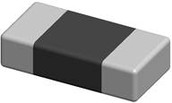
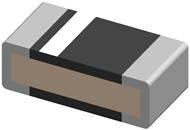
Chip Ferrite Bead A chip ferrite bead is a surface-mount passive component used as a low-pass filter to suppress high-frequency noise, specifically Electromagnetic Interference (EMI) and Radio Frequency Interference (RFI), in electronic circuits. It works by absorbing unwanted high-frequency energy and dissipating it as a small amount of heat.
Function and Operation Unlike a standard inductor which stores energy in a magnetic field, a ferrite bead is engineered to be a frequency-dependent resistor. - Noise Suppression: It is placed in series with a power or signal line to block differential mode noise.
- Energy Conversion: The ferrite material's magnetic properties cause the high-frequency noise signal's energy to be converted into thermal energy (heat), effectively filtering out the interference.
- Frequency Dependence: At low frequencies (DC or desired signal frequencies), the ferrite bead has a very low impedance (low DC resistance), allowing the signal or power to pass through with minimal impact. As the frequency increases into the noise spectrum, its impedance increases significantly, primarily due to its resistive properties, thereby blocking the noise.
Key Characteristics - Construction: Chip ferrite beads are made from a ceramic compound composed of iron, nickel, and zinc oxides, typically using multilayer construction techniques.
- Impedance Profile: Datasheets for ferrite beads show an impedance (Z) versus frequency graph, highlighting inductive (X) and resistive (R) components. For optimal noise filtering, the bead should be selected so that its resistive component is maximized at the specific noise frequency requiring attenuation.
- DC Bias Effect: The performance of a ferrite bead is highly dependent on the DC current flowing through it. Applying a large DC current can saturate the ferrite material, significantly reducing its impedance and filtering effectiveness. Designers often operate them at about 20% of their rated current to maintain performance.
- Combination with Capacitors: Ferrite beads are commonly combined with decoupling capacitors to form low-pass filter networks (often a Pi-filter configuration) to more effectively reduce a wide range of power supply noise.
Applications Chip ferrite beads are widely used to ensure electromagnetic compatibility (EMC) and improve signal integrity in sensitive electronic devices. - Power Supply Lines: Suppressing high-frequency switching noise from DC-DC converters and power rails.
- Signal and Data Lines: Cleaning noise on general signal lines and high-speed data interfaces like USB and HDMI to prevent data corruption or interference (autointoxication).
- Integrated Circuit Protection: Placed near the pins of integrated circuits to suppress parasitic oscillations and enhance circuit reliability.
- Automotive and Medical Equipment: Used in systems where reliable operation and freedom from interference are critical for safety and performance.
Chip Filter A chip filter, typically a surface-mount device (SMD), is an electronic component or an integrated circuit (IC) designed to selectively pass signals of certain frequencies while blocking or attenuating others. They are critical for managing the flow of electrical signals and reducing unwanted noise in modern, compact electronic systems.
Function
Filters work by manipulating the flow of electrical current through components like resistors, capacitors, and inductors, which react differently to various frequencies. - Signal Integrity: The primary role is to improve signal quality by removing noise or isolating specific frequency bands, which is essential for systems like audio processing and radio communications.
- Frequency Management: They define a "passband" (frequencies allowed through) and a "stopband" (frequencies blocked), shaping the frequency response of a circuit.
- Miniaturization: Chip filters, whether discrete passive components (like an LC filter combining an inductor and capacitor on a single chip) or complex integrated circuits, enable dense circuit board designs with improved performance and reduced parasitic effects compared to larger, through-hole components.
Types of Chip Filters Chip filters are classified based on the frequency range they affect and their internal design (active or passive). - By Frequency Response:
- Low-Pass Filter: Passes low-frequency signals and blocks higher frequencies (e.g., in power supplies to smooth DC voltage).
- High-Pass Filter: Passes high-frequency signals and blocks lower frequencies (e.g., in communication systems to block DC bias).
- Band-Pass Filter: Passes only a specific range of frequencies while blocking those above and below (e.g., in radio tuners to select a specific station).
- Band-Stop (Notch) Filter: Blocks a specific range of frequencies but allows all others to pass (e.g., to eliminate specific interference or hum).
- By Design Type:
- Passive Filters: Built using only resistors, capacitors, and inductors; they don't require an external power source and generally have simple designs.
- Active Filters: Incorporate active components like operational amplifiers (op-amps) along with resistors and capacitors to provide signal amplification and improved stability, typically used for lower frequencies.
- Integrated Circuit (IC) Filters: Full filter circuits integrated into a single semiconductor chip, often including advanced designs like Butterworth or Chebyshev responses.
Applications Chip filters are fundamental to virtually all non-trivial electronic systems. - Audio Systems: Used for tone control, speaker crossover networks, and noise reduction.
- Communication Devices: Essential for channel selection, signal separation in 5G networks, Wi-Fi, and Bluetooth, ensuring clean data transmission.
- Power Electronics: Suppress voltage spikes, reduce electromagnetic interference (EMI), and smooth power supplies. For example, a Murata BNX02 SMD EMI Filter is an LC combined filter used to suppress noise in automotive applications.
- Data Processing: Placed in front of analog-to-digital converters (ADCs) to reduce aliasing and ensure signal integrity.
Chip Fuse A chip fuse is a miniature, surface-mount device (SMD) designed to protect electronic circuits from damage caused by excessive current. They are essential safety devices that interrupt the flow of electricity when current exceeds a predetermined limit, preventing damage to downstream components and potential fire hazards.
Function and Operation The operation of a chip fuse is based on the heating effect of current. It contains a precise metallic or thin-film conductive element designed to melt and break the circuit when subjected to overcurrent conditions. - Normal Operation: Under normal current flow, the fuse element generates a small amount of heat that is efficiently dissipated, allowing the circuit to operate normally.
- Overcurrent Event: If the current suddenly surges beyond the fuse's rated ampere limit (due to a short circuit or overload), the increased heat causes the internal element to quickly reach its melting point and melt (or "blow").
- Circuit Interruption: The melting of the element creates an open circuit, instantly stopping the flow of current and isolating the power source from the delicate components it protects.
- Single-Use vs. Resettable: Traditional single-use chip fuses must be replaced after they blow. Resettable chip fuses (PPTC or polymeric positive temperature coefficient fuses) use a polymer material that temporarily changes to a high-resistance state when overheated, and then resets once the fault is cleared and the component cools down.
Types of Chip Fuses Chip fuses are primarily categorized by their response speed to overcurrent events: - Fast-Acting Fuses: These are designed to blow very quickly in response to overcurrent conditions and are suitable for protecting components that are highly sensitive to overcurrent, such as integrated circuits.
- Slow-Blow (Time-Delay) Fuses: These are designed with a time delay to withstand transient inrush currents or momentary surges that occur when equipment is first powered on (common in circuits with motors or large capacitors), but still interrupt the circuit during a prolonged overload.
Applications The ultra-compact size and reliability of chip fuses make them a standard component in modern, high-density electronics. Common applications include: - Consumer Electronics: Smartphones, laptops, digital cameras, and game consoles.
- Power Management: Protecting lithium-ion battery packs and DC-to-DC converters.
- Automotive Electronics: Safeguarding sensitive in-car circuits from voltage spikes and overcurrent conditions.
- Industrial and Medical Devices: Used where space efficiency and reliable, precise protection are mandatory for safety and performance.
When selecting a chip fuse, designers must consider factors such as the normal operating current, maximum voltage rating, fusing current, and specific time-current characteristics to ensure optimal protection for the circuit.
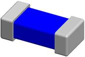
Chip Inductor A chip inductor, also known as a surface-mount device (SMD) inductor, is a compact electronic component that stores energy in a magnetic field when an electric current flows through it. Chip inductors are crucial for managing power, filtering signals, and creating resonant circuits in modern, miniaturized electronic devices like smartphones and laptops.
Function and Operation Inductors operate on the principle of electromagnetic induction. When current flows through a coiled conductor, a magnetic field is generated around it. - Opposing Current Changes: The key function of an inductor is to resist changes in the current flow. When current increases, the growing magnetic field produces a "back electromotive force" (back EMF) that opposes the increase. When current decreases, the magnetic field collapses and releases stored energy back into the circuit, trying to maintain a steady flow.
- Filtering (Choke Function): Because inductors resist high-frequency changes, they are effective at blocking high-frequency AC signals or noise while allowing DC or lower-frequency signals to pass. This is a core function in power supplies and communication systems.
- Energy Storage: Inductors temporarily store electrical energy in their magnetic fields, releasing it when needed. This is a crucial property for applications like DC-DC power converters.
- Impedance: In AC circuits, the inductor's impedance (resistance to current flow) increases with frequency, a characteristic used for frequency-sensitive filtering and tuning.
Types of Chip Inductors Chip inductors are manufactured using various techniques to optimize performance for specific frequency ranges and power requirements. - Wire-Wound Type:
- Description: A fine insulated wire is wound around a core material, often ceramic or ferrite.
- Characteristics: Known for a wide range of inductance values, high quality factor (Q), and high current handling capacity.
- Applications: Used in RF circuits and power circuits where high performance is needed.
- Multilayer (Laminated) Type:
- Description: Made by alternately printing and laminating layers of ferrite or ceramic material with conductive patterns to form an internal coil with a closed magnetic circuit.
- Characteristics: Very small, excellent magnetic shielding (reduces interference with neighboring components), suitable for high-density installation.
- Applications: Common in mobile phones, wireless LANs, and high-frequency digital signal processing equipment due to their compact size and good high-frequency characteristics.
- Film Type:
- Description: Created using thin-film deposition technology, with electrodes concentrated on a single layer.
- Characteristics: Offers high precision, high stability, and maintains a high Q value in the microwave frequency band.
- Applications: Suited for highly precise high-frequency and microwave applications where stability is critical.
Applications Chip inductors are integral to modern electronic design. - Power Management ICs: Used in DC-DC converters and voltage regulators for voltage conversion, filtering, and energy storage.
- RF (Radio Frequency) Circuits: Essential in wireless communication devices, transceivers, and antennas for signal processing, impedance matching, and filtering at high frequencies.
- Signal Filtering: Used with capacitors to form LC filters, which isolate and filter AC signals and reduce unwanted noise in signal lines.
- Resonant and Timing Circuits: Paired with capacitors and resistors to form tuning or oscillator circuits that generate precise frequencies for system clocks and radio tuning.
- Data Lines: Common mode chip inductors are used on high-speed data lines (USB 2.0, HDMI, LVDS) to suppress common-mode noise without distorting the high-speed signal transmission.
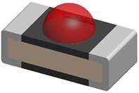
Chip LED A chip LED, also known as a surface-mount device (SMD) LED, is a compact electronic component that emits light when an electric current passes through it. These are the core light-generating units in modern lighting and display technologies, valued for their small size, high efficiency, and versatility.
Function and Operation LED stands for Light Emitting Diode, and its operation is based on the principles of semiconductors. - Electroluminescence: The core of the chip LED is a semiconductor chip (or die) made of materials like gallium nitride or gallium phosphide. This chip contains a p-n junction.
- Current Flow: When a voltage is applied in the forward direction (positive to anode, negative to cathode), electrons and "holes" (positive charge carriers) are pushed toward the junction.
- Photon Emission: The electrons and holes recombine at the junction, releasing energy in the form of photons (light). The color of the light produced depends on the specific semiconductor materials used.
- Packaging: The semiconductor chip is typically encased in a plastic or ceramic package that protects it from damage and helps to focus the light output. A phosphor layer is often used with a blue-light emitting chip to create white light.
Common Types of Chip LEDs Chip LEDs are often identified by a four-digit number that indicates their physical dimensions in millimeters (e.g., a 5050 chip is 5.0mm x 5.0mm). - SMD (Surface-Mounted Device) LEDs: The most common type, these are individual chips soldered directly onto the PCB. They are highly versatile and can contain multiple diodes (e.g., three diodes in a 5050 package to create RGB color mixing).
- COB (Chip-on-Board) LEDs: Multiple small LED chips (often nine or more) are packed closely together on a single substrate to form a lighting module.
- Features: Provides high light intensity, a uniform light appearance (less glare), and good thermal management due to direct mounting on a heat-conducting substrate.
- Applications: Used in high-power applications like floodlights, street lights, and downlights.
Applications The compact size, high efficiency, and durability of chip LEDs make them suitable for a vast array of applications across many industries. - Consumer Electronics: Used for display backlighting in smartphones, tablets, and TVs, as well as indicator lights in various gadgets and wearables.
- General Illumination: Widely employed in residential, commercial, and industrial lighting, including household bulbs, office panels, and street lighting.
- Automotive Lighting: Integrated into headlights, taillights, interior lighting, and dashboard indicators due to their reliability and low power consumption.
- Horticulture and Medical: Specialized chip LEDs emitting specific wavelengths are used in grow lights to optimize plant growth and in surgical lighting where precision is critical.
- Displays and Signage: Form the pixels in large LED walls and digital billboards, delivering high visibility and vivid colors.
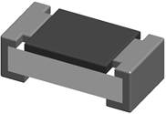
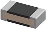
Chip Resistor A chip resistor, also known as a surface-mount device (SMD) resistor, is a small electronic component used in circuits to control current flow, divide voltage, or terminate signals. Unlike larger through-hole resistors, they mount directly onto a printed circuit board (PCB), allowing for more compact designs and automated manufacturing.
Function and Operation Chip resistors operate based on Ohm's Law, using a resistive element to oppose electrical current. Their functions include: - Current Limiting: Used in series with components like LEDs to protect them from excessive current.
- Voltage Dividing: Connecting resistors in series can create a lower, proportional voltage.
- Current Detection: By measuring voltage drop across a low-resistance chip resistor, current can be monitored.
- Biasing: Providing necessary voltage levels to semiconductor components for proper operation and signal conditioning.
Types of Chip Resistors by Technology Chip resistors are typically made using two main methods, each with different properties: - Thick Film Resistors: These use a resistive paste screen-printed onto a ceramic base. They are common, cost-effective, and suitable for general uses where high precision is not essential.
- Thin Film Resistors: These involve depositing a very thin metallic layer onto an insulating material. They offer higher precision, better stability, tighter tolerances, and lower noise but are more expensive. They are used in sensitive applications like medical equipment and scientific instruments.
A chip thermistor is a surface-mount device (SMD) that acts as a thermally sensitive resistor, changing its electrical resistance in response to temperature changes. They are essential for temperature sensing, control, and circuit protection in compact modern electronics.
Function and Operation The term "thermistor" is a blend of "thermal" and "resistor". They are typically made from a pressed and sintered mixture of metal oxides (like manganese, nickel, cobalt, and iron oxides) and coated in materials like epoxy or glass for protection. Chip thermistors are generally integrated into a voltage divider circuit to convert the resistance change into a measurable voltage signal that can be interpreted as a temperature reading.
Types of Chip Thermistors The two main categories of thermistors are defined by their temperature coefficient: - NTC (Negative Temperature Coefficient) Thermistors: The resistance decreases as the temperature increases.
- Primary Use: Temperature measurement, sensing, and compensation (e.g., in digital thermometers, thermostats, HVAC systems, and battery management systems). They are also used as inrush current limiters, presenting high initial resistance that drops as they heat up during normal operation.
- PTC (Positive Temperature Coefficient) Thermistors: The resistance increases as the temperature increases.
- Primary Use: Circuit protection and self-regulating heaters. When the current becomes excessive and the thermistor heats up, its resistance rapidly increases, limiting the current flow and acting as a resettable fuse.
Applications Due to their high sensitivity and fast response time within specific temperature ranges, chip thermistors are used in numerous applications. - Temperature Measurement: Monitoring engine coolant or oil temperature in automotive systems.
- HVAC Systems: Regulating temperature in air conditioners and refrigerators.
- Consumer Appliances: Found in coffee makers, hair dryers, and toasters for precise temperature control.
- Circuit Protection: PTC types are used to protect sensitive telecom apparatus and motors from overcurrent.
- Medical Devices: Used in applications requiring precise temperature control and monitoring.
Chip Varistor A chip varistor, or surface-mount device (SMD) varistor, is a voltage-dependent resistor (VDR) used to protect electronic circuits from sudden, transient overvoltages such as electrostatic discharge (ESD) and lightning-induced surges. It acts as a safety device by automatically diverting excess current away from sensitive components.
Function and Operation The name "varistor" is a combination of "variable" and "resistor", accurately describing its core function. - High Resistance (Normal Operation): Under normal operating voltage, a chip varistor has very high resistance, behaving almost like an open circuit and allowing only a negligible leakage current to flow.
- Low Resistance (Surge Event): When a voltage surge exceeds a specific threshold voltage (known as the varistor voltage or clamping voltage), the varistor's internal resistance drops dramatically.
- Voltage Clamping: This rapid drop in resistance allows the varistor to conduct the large surge current safely to ground or another part of the circuit, effectively "clamping" the voltage to a safe level and protecting downstream components.
- Bidirectional Protection: Unlike zener diodes, most varistors are bidirectional and can suppress voltage spikes in both positive and negative directions, making them suitable for both AC and DC circuits.
Construction Chip varistors are typically multilayer ceramic devices made from zinc oxide (ZnO) material pressed between metal electrodes using a multilayering process. The numerous grain boundaries within the ceramic material provide the non-linear voltage-current characteristics.
Key Characteristics - Fast Response Time: Chip varistors react very quickly to surges, often within nanoseconds (300 to 700 picoseconds), suppressing the overvoltage before it reaches its peak.
- Compact Size: As SMD components, they have a small footprint, enabling installation in miniature and high-density electronic devices.
- Noise Suppression: They inherently possess some capacitance and can offer noise suppression effects, sometimes replacing a combination of a TVS diode and a capacitor for EMI filtering in a single component.
Applications
Chip varistors are widely used across various electronic sectors for circuit protection. - Consumer Electronics: Found in smartphones, computers, and tablets for ESD protection on I/O ports, buttons, and connecting terminals.
- Automotive Electronics: Protect sensitive control units (ECUs) and communication buses (CAN, LIN) from voltage spikes and surges generated by ignition systems or inductive loads.
- Power Supplies: Installed in AC power supplies and adapters to guard against surges from the main power line.
- Industrial Equipment: Protect control panels, motors, and automation systems from switching surges and electrical noise.
 PCB Footprint Expert Simplify your PCB design process with the Footprint Expert, the ultimate tool for automating staggered pin BGAs. Automation helps ensures accurate, consistent, reliable footprints with minimal introduction of human error. Let the Footprint Expert handle your CAD library so you can focus on creating flawless PCB designs faster and more efficiently!
Get your FREE Footprint Calculator or Footprint Expert Evaluation License: Call: 847-557-2300
|


 Post Options
") Thanks(0)
Thanks(0)
 Quote
Quote  Topic: Chips
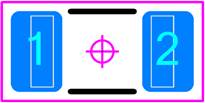


 Topic Options