

|
|
0201 Capacitor Corner Radius Pad |
Post Reply 
|
| Author | |
dramos 
Advanced User 
Joined: 18 Feb 2021 Status: Offline Points: 101 |
 Post Options Post Options
") Thanks(0) Thanks(0)
 Quote Reply Quote Reply
 Topic: 0201 Capacitor Corner Radius Pad Topic: 0201 Capacitor Corner Radius PadPosted: 07 Apr 2026 at 4:09am |
|
Hi all,
I created my first 0201 capacitor and I feel that using a Corner Radius Size Limit parameter= 0.10 mm could be "risky" (I used Fab Tol= 0, Placement Tol=0). 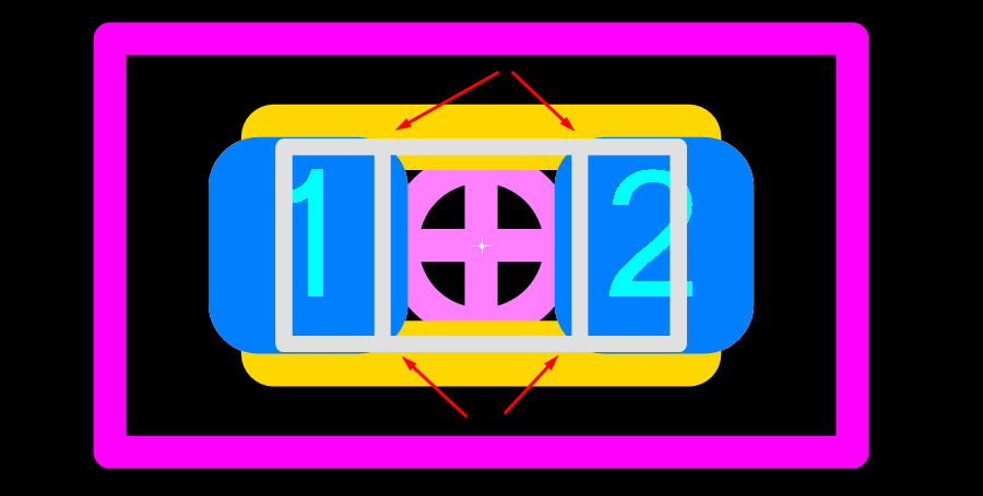 I know that some manufacturers use 0.05 mm. My component is GRM033R61C104KE14D from Murata Which is your recommendation for this tiny component sizes? Waiting for your comments. David |
|
 |
|

|
|
|
|
|
Tom H
Admin Group 

Joined: 05 Jan 2012 Location: San Diego, CA Status: Offline Points: 6075 |
Post Options
Thanks(0)
Quote Reply
Posted: 07 Apr 2026 at 8:30am |
|
Rule of thumb - any package less than 1.00 mm in length or width should have 0.05 mm corner radius pads.
You can use the 'SMD Pad Stack Rules' in the side panel of the calculator to change the corner radius. Or you can move the calculator footprint to FP Designer to permanently save the 0.05 mm corner radius to FPX library format. But we recommend that you first setup everything in the calculator before moving to FP Designer so you won't have to edit the pad stack in FP Designer. FP Designer saves all your settings to the FPX library. You can rename the Footprint Name in the Library Editor. |
|
|
|
|
dramos
Advanced User
Joined: 18 Feb 2021 Status: Offline Points: 101 |
Post Options
Thanks(0)
Quote Reply
Posted: 08 Apr 2026 at 2:59am |
|
Hi Tom and Team,
Many thanks for your fast response. Does it mean that we should apply the same rule of thumb to 0402 case components or even 0603 components? I am thinking on resistors ... Thanks for spreading your knowledge :) david
|
|
|
|
|
Tom H
Admin Group
Joined: 05 Jan 2012 Location: San Diego, CA Status: Offline Points: 6075 |
Post Options
Thanks(0)
Quote Reply
Posted: 08 Apr 2026 at 8:41am |
|
0402 is not 'Less than 1.00 mm'.
It looks OK with a 0.10 mm corner radius.  Watch out for excessive package tolerances. This package is 1.00 L x 0.50 W x 0.55 H with a 0.10 tolerance on all dimensions. |
|
|
|
|
dramos
Advanced User
Joined: 18 Feb 2021 Status: Offline Points: 101 |
Post Options
Thanks(0)
Quote Reply
Posted: 08 Apr 2026 at 9:12am |
|
Hi Tom and Team,
Thanks for the clarification, when you mentioned length , width I was surprised if you were referring to any of the values. I was a little bit in shock!! hahahahaha Thanks and regards, david
|
|
|
|
|
Post Reply
|
|
| Tweet |
| Forum Jump | Forum Permissions You cannot post new topics in this forum You cannot reply to topics in this forum You cannot delete your posts in this forum You cannot edit your posts in this forum You cannot create polls in this forum You cannot vote in polls in this forum |


 Topic Options