0201 Capacitor Corner Radius Pad
Printed From: PCB Libraries Forum
Category: Libraries
Forum Name: Footprints / Land Patterns
Forum Description: [General or a CAD specific issues / discussions]
URL: https://www.PCBLibraries.com/forum/forum_posts.asp?TID=3631
Printed Date: 26 Jul 2026 at 7:36am
Topic: 0201 Capacitor Corner Radius Pad
Posted By: dramos
Subject: 0201 Capacitor Corner Radius Pad
Date Posted: 07 Apr 2026 at 4:09am
|
Hi all, I created my first 0201 capacitor and I feel that using a Corner Radius Size Limit parameter= 0.10 mm could be "risky" (I used Fab Tol= 0, Placement Tol=0). 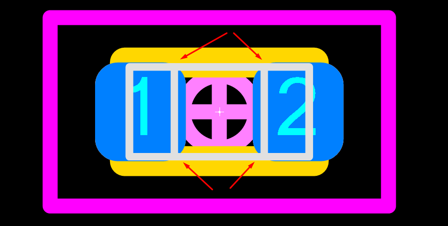 I know that some manufacturers use 0.05 mm. My component is GRM033R61C104KE14D from Murata Which is your recommendation for this tiny component sizes? Waiting for your comments. David |
Replies:
Posted By: Tom H
Date Posted: 07 Apr 2026 at 8:30am
|
Rule of thumb - any package less than 1.00 mm in length or width should have 0.05 mm corner radius pads. You can use the 'SMD Pad Stack Rules' in the side panel of the calculator to change the corner radius. Or you can move the calculator footprint to FP Designer to permanently save the 0.05 mm corner radius to FPX library format. But we recommend that you first setup everything in the calculator before moving to FP Designer so you won't have to edit the pad stack in FP Designer. FP Designer saves all your settings to the FPX library. You can rename the Footprint Name in the Library Editor. ------------- Stay connected - follow us! https://twitter.com/PCBLibraries" rel="nofollow - X - http://www.linkedin.com/company/pcb-libraries-inc-/" rel="nofollow - LinkedIn |
Posted By: dramos
Date Posted: 08 Apr 2026 at 2:59am
|
Hi Tom and Team, Many thanks for your fast response. Does it mean that we should apply the same rule of thumb to 0402 case components or even 0603 components? I am thinking on resistors ... Thanks for spreading your knowledge :) david
|
Posted By: Tom H
Date Posted: 08 Apr 2026 at 8:41am
|
0402 is not 'Less than 1.00 mm'.
It looks OK with a 0.10 mm corner radius.  Watch out for excessive package tolerances. This package is 1.00 L x 0.50 W x 0.55 H with a 0.10 tolerance on all dimensions. ------------- Stay connected - follow us! https://twitter.com/PCBLibraries" rel="nofollow - X - http://www.linkedin.com/company/pcb-libraries-inc-/" rel="nofollow - LinkedIn |
Posted By: dramos
Date Posted: 08 Apr 2026 at 9:12am
|
Hi Tom and Team, Thanks for the clarification, when you mentioned length , width I was surprised if you were referring to any of the values. I was a little bit in shock!! hahahahaha Thanks and regards, david
|