Assembly Polarity Markings & Scaling
Printed From: PCB Libraries Forum
Category: PCB Footprint Expert
Forum Name: Standard Components
Forum Description: component families of the Footprint Expert
URL: https://www.PCBLibraries.com/forum/forum_posts.asp?TID=3625
Printed Date: 24 Jul 2026 at 8:28pm
Topic: Assembly Polarity Markings & Scaling
Posted By: Tom H
Subject: Assembly Polarity Markings & Scaling
Date Posted: 10 Mar 2026 at 7:36pm
|
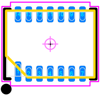
Pin 1 polarity markings generally include
a Dot, Circle, Chamfer and Bar. Indicators scale themselves to the part size within user defined in combination with or hard-coded minimum and maximum limits.
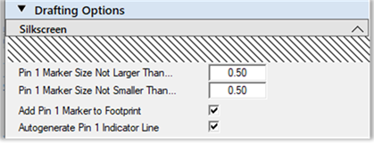
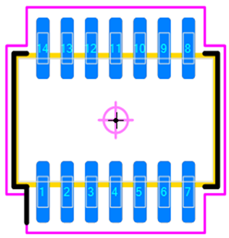
The Silkscreen Dot diameter is
equal to the lesser of the ordinary pad length or width, not smaller than the
silkscreen polarity Marker minimum, nor greater than the Marker maximum.
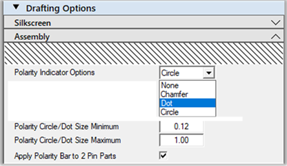
An additional silkscreen option to Autogenerate a Pin 1 Indicator Line is available for certain parts where it can be practically applied. In such cases an extension is applied to the silkscreen outline near the pin one location. The Assembly Dot or Circle
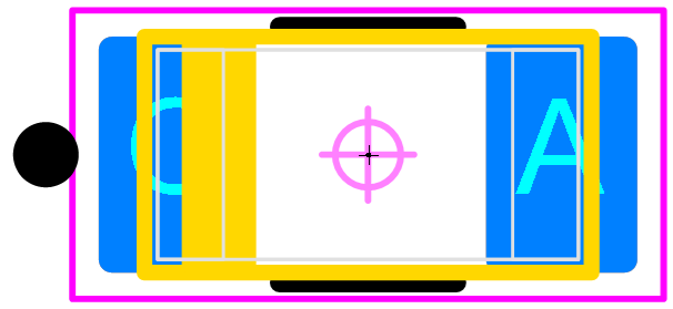
diameter is equal to 1/2 the lesser of body length or width, not less than the
assembly circle/dot minimum nor greater than maximum limits.
The assembly outline chamfer is
equal to 1/3 the lesser of body length or width, not greater than 1.00 mm.
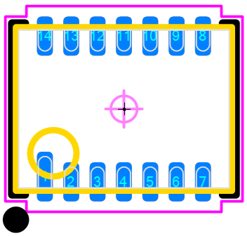
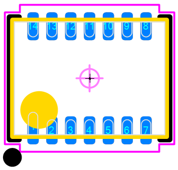
Silkscreen Dot with an Assembly Dot and Circle:
The Chamfer is equal to 1/3 the lesser of body dimension and not to exceed a maximum of 1.00 mm. Example: if the minimum body dimension is 1.60 mm, the chamfer size will be 1/3 less or 0.53 mm. Silkscreen Dot with an Assembly
Chamfer and a Silkscreen Pin 1 Indicator Line:
The assembly polarity bar is only an option for two pin polarized part types. Bar width is equal to the lesser of 1 mm or 1/6 the body width. The assembly polarity bar is applied instead the chamfer, dot or circle its option is checked. Silkscreen Dot with an Assembly
Polarity Bar :
You select the type of assembly polarity marking and it will be applied to all your footprint patterns. This will add consistency to your PCB library assembly polarity markings. ------------- Stay connected - follow us! https://twitter.com/PCBLibraries" rel="nofollow - X - http://www.linkedin.com/company/pcb-libraries-inc-/" rel="nofollow - LinkedIn |