FPX File Definition
Printed From: PCB Libraries Forum
Category: Libraries
Forum Name: PCB Libraries Guideline
Forum Description: (online edition)
URL: https://www.PCBLibraries.com/forum/forum_posts.asp?TID=3690
Printed Date: 05 Oct 2026 at 5:16am
Topic: FPX File Definition
Posted By: Nick B
Subject: FPX File Definition
Date Posted: 20 Aug 2026 at 11:00am
|
The FPX file library is a collection of package dimensions for standard parts and manufacturers recommend patterns for non-standard parts. Standard part footprints are created in the calculator using one of the 144 surface mount or through-hole templates. Non-standard parts are created using the FP Designer module in Footprint Expert. All connectors are non-standard parts except headers that have a symmetrical pad pattern with one pad stack and the pins are evenly placed using the same X/Y grid system. Any semiconductor that requires more than one pad stack length or width is a non-standard package. Any discrete component that its terminal lead form is not listed in the surface mount standard terminal leads is considered a non-standard package. The Calculators save this information in the FPX file library:
All other footprint features are generated in Tools > Options. When you open a FPX file calculator part, the package dimensions will auto-populate the package dimensions in the correct cells. The resulting footprint is derived by combining the package dimensions with the Terminal Solder Joint Goal Settings for that component family and the Drafting Rule Settings for silkscreen, assembly, courtyard, component, terminal and origin outlines. The package and terminal tolerances also play a role in the pad stack calculation. You can create multiple Option files with different rule settings and use the same FPX file to create multiple libraries. Set up Options to solder mask define pad stacks for Flex circuits. Or set up rules with larger solder joint goals for Wave Solder. Or create an Option file with rules from an assembly shop or rules for a specific customer. Use the same FPX file to create multiple libraries for different applications. For non-standard FP Designer parts, a lot more data is saved in the FPX file. FP Designer footprint data that is saved in the FPX file include:
The FPX file comes with these column headers, but you can add additional columns:
The FPX file has built in features that help automate and organize library data. When you select a Calculator component family and enter the package dimensions and Save to FPX Library, Footprint Expert autogenerates the Footprint Name, Physical Description, Mounting Type, Part Status and Footprint Date. The Manufacturer Names are embedded into the program. When the Manufacturer cell is selected, just enter the first couple letters of the Manufacturer Name and a list of Manufacturers appear in a dropdown menu selection. By typing a 'T' in the Manufacturer cell, every manufacturer name that begins with 'T' will appear in the dropdown menu. 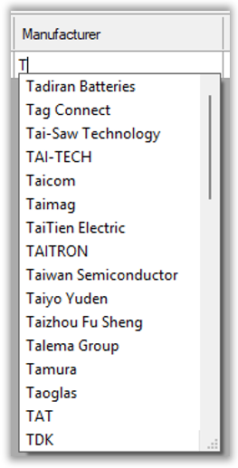 Type 'TE' and the list will only include manufacturer names that include 'TE'. 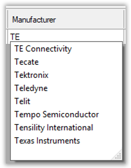 Type 'TEX' and the list will only include manufacturer names that include 'TEX'. Texas Instruments is the only manufacturer that begins with TEX. Select Texas Instruments and it will auto-populate the Manufacturer cell.  This will ensure that all the spelling of every manufacturer is consistent. 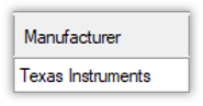 The Case Code and Part Number must be manually entered or copy/paste from a datasheet. Once the full Part Number is populated, you can Right Mouse Click that cell and a dropdown menu will appear with these options: 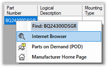 When 'Internet Browser' is selected, the default web browser will display all the websites that support that Part Number. When 'Parts on Demand (POD)' is selected, the default browser will open www.pcblibraries.com/POD allowing you to download that part into your /downloads folder. Then you can import the FPX file into your Master Library and create the footprint out to your CAD tool. When 'Manufacturer Home Page' is selected, the main page to that Manufacturer will open in your default browser., You can copy/paste the part number into the search box to locate the datasheet. Note: The Part Number search requires the Manufacturer Name cell to be populated. The same feature is available if you have the correct Case Code cell entered. The 'Datasheet' cell can be https:// or a network drive path to a PDF datasheet. The 'Mounting Type' cell can be auto populated by entering a S for Surface Mount or T for Through-hole or M for Mixed Technology. Here are the control features for the Library Editor. 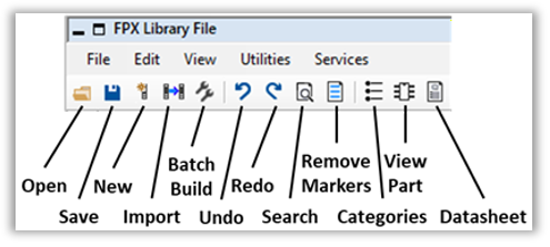
Delete a Row by selecting the gray button to the left of the Footprint Name and Right Mouse Click and select 'Delete Row'. Add a new blank row by Right Mouse Click and select 'New - Row' or 'New - Rows'. Add a new column by Right Mouse Click and select 'New - Column'. Create as many columns as you need. 
 The Footprint Expert automates footprints to perfection. Professional, detailed, and accurate parts - all built consistently with identical rules, regardless of how many people are involved in your library development. Get your FREE Footprint Calculator or Footprint Expert Evaluation License: https://www.pcblibraries.com/Register" target="_blank rel="nofollow" - https://www.PCBLibraries.com/Register Call us - 847-557-2300 ------------- Stay connected - follow us! https://twitter.com/PCBLibraries" rel="nofollow - X - http://www.linkedin.com/company/pcb-libraries-inc-/" rel="nofollow - LinkedIn |