|
|
Assembly Polarity Markings & Scaling |
Post Reply 
|
| Author | |
Tom H 
Admin Group 

Joined: 05 Jan 2012 Location: San Diego, CA Status: Offline Points: 6026 |
 Post Options Post Options
") Thanks(0) Thanks(0)
 Quote Reply Quote Reply
 Topic: Assembly Polarity Markings & Scaling Topic: Assembly Polarity Markings & ScalingPosted: 12 hours 19 minutes ago at 7:36pm |
|
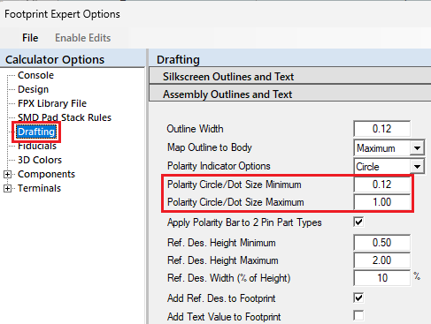
The assembly pin 1 polarity markings include a Dot, Circle, Chamfer and Bar. Polarity indicators scale themselves to the part size within defined user or hard-coded minimum and maximum limits. The dot and circle sizes are equal to the lesser of body length or width, not to exceed the circle/dot minimum and maximum limits. Here are the Options for setting
the minimum & maximum assembly polarity Circle/Dot sizes.
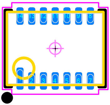
The Circle/Dot sizes automatically scale per the minimum body dimension. Here is a sample of an Assembly Polarity
Circle:
Here is a sample of an Assembly Polarity Circle:
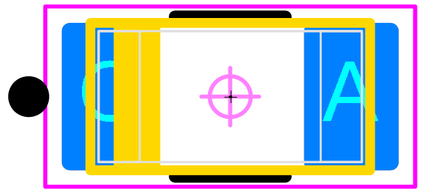
The Chamfer is equal to 1/3 the lesser of body dimension and not to exceed a maximum of 1.00 mm. Example: if the minimum body dimension is 1.60 mm, the chamfer size will be 1/3 less or 0.53 mm. Here is a sample of an Assembly Polarity
Chamfer:
The Polarity Bar is equal to 1/6 the package body width, not less than 0.25 mm or more than 1mm max. The Polarity Bar is limited to polarized 2-pin packages including Capacitors, Diodes, LEDs and Antennas. Here is a sample of an Assembly Polarity Bar:
You select the type of assembly polarity marking and it will be applied to all your footprint patterns. This will add consistency to your PCB library assembly polarity markings. |
|
 |
|

|
|
|
|
|
Post Reply
|
|
| Tweet |
| Forum Jump | Forum Permissions You cannot post new topics in this forum You cannot reply to topics in this forum You cannot delete your posts in this forum You cannot edit your posts in this forum You cannot create polls in this forum You cannot vote in polls in this forum |


 Topic Options